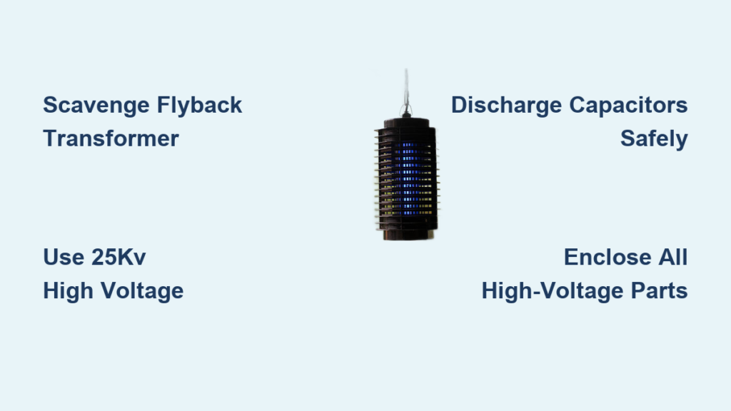
That relentless buzzing near your patio light or kitchen window isn’t just annoying—it’s stealing your peace and potentially spreading disease. Mosquitoes, flies, and other pests thrive in warm months, but commercial bug zappers cost $30-$100 and often underperform. What if you could build a more effective electric bug zapper for under $15 using parts from old electronics? This DIY project creates a lethal 25,000-volt grid that eliminates insects on contact. While working with high voltage demands extreme caution, this guide walks you through every step safely. You’ll gain a custom-built pest control solution that outperforms store-bought models while understanding the electronics behind this satisfying zap.
Before touching a single component, acknowledge this critical truth: the high-voltage circuit in your bug zapper can deliver a lethal shock. This isn’t theoretical—flyback transformers from CRT devices generate over 25,000 volts. If you’re under 18, uncomfortable with electronics, or unwilling to follow every safety step, buy a commercial unit instead. This guide prioritizes your safety above all else. When completed correctly, your zapper will have all high-voltage components fully enclosed with only the insect-killing grid exposed behind protective shielding. Let’s gather what you need to build this essential summer tool.
Essential Parts List for Your Homemade Bug Zapper Build
Skip generic “tools you’ll need” lists—here’s exactly what to source for a functional, safe zapper. Start with the heart of the system: a flyback transformer scavenged from an old CRT monitor or television (not the small one from a radio). You’ll need two 1N4007 high-voltage diodes ($0.50 each) and a 1000-2000pF, 3-6kV capacitor ($2) for voltage smoothing. The oscillator circuit requires a TIP122 NPN Darlington transistor ($1.50), 1kΩ resistor ($0.10), and 0.1µF capacitor ($0.25). For safety, include a 1MΩ resistor ($0.10) to discharge capacitors and a 300Ω, 5-watt resistor ($0.30) to limit current.
Power comes from a 9V battery with on/off switch ($3) or 12V DC adapter. For the zapping grid, use fine stainless steel mesh ($5) with 6mm (1/4-inch) spacing between wires—critical for insect-sized gaps that prevent accidental contact. Enclosure materials include PVC pipe or plastic project box ($4) and polycarbonate sheet ($6) for the protective cage. Never substitute components; incorrect parts cause dangerous arcing or failure.
Critical Safety Precautions Before Circuit Assembly
Treat every step as if the circuit is live—even when unplugged. Capacitors store lethal charges for hours after power-off, so always discharge them using an insulated screwdriver with a wire connected to ground before touching components. Work on a non-conductive surface like wood (never metal), wear rubber-soled shoes, and use 1000V-rated insulated gloves during testing. The golden rule: keep one hand in your pocket while probing to prevent current crossing your heart. Never work alone—have someone nearby with a non-conductive rescue tool (like a dry wooden broom handle) in case of shock.
Most critical mistakes happen during rushed assembly: using frayed wires, skipping capacitor discharge, or exposing high-voltage points. Double-check every connection against circuit diagrams before powering on. If you smell ozone or see sparks outside the grid, disconnect immediately—this indicates dangerous arcing. Remember: commercial zappers cost more because they’ve engineered out these risks. Your DIY version demands heightened vigilance at every stage.
Building the High-Voltage Circuit: Step-by-Step Assembly
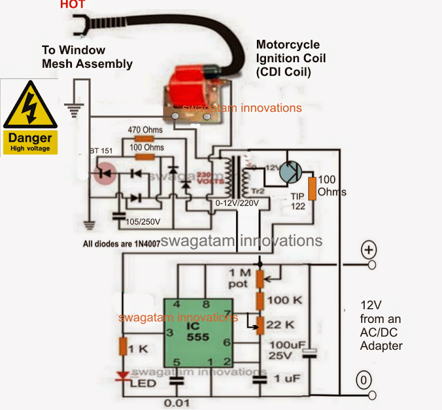
This oscillator circuit converts 9V DC into insect-killing voltage. Never power this section until fully enclosed in its housing. Start by soldering the 9V battery’s positive terminal to one end of the 1kΩ resistor. Connect the resistor’s free end to the TIP122 transistor’s base pin. Attach the transistor’s emitter directly to the battery’s negative terminal (ground). Now link the transistor’s collector to one end of the flyback transformer’s primary winding (usually the thicker wires).
Complete the oscillator by connecting the 0.1µF capacitor between the collector and emitter pins. For safety, add the 1MΩ resistor across the high-voltage capacitor leads to ensure automatic discharge when off. Visual check: All connections should be clean, soldered joints with no stray wire strands. Test continuity with a multimeter before proceeding—any short circuit here could destroy components instantly. When powered, you’ll hear a high-pitched whine; if silent, check transistor orientation (pins: base, collector, emitter).
Constructing the Insect-Zapping Grid Frame
Your grid spacing determines effectiveness—too wide and insects escape; too narrow and arcs won’t form. Cut two identical rectangles of PVC pipe (6″x4″ works for most builds) to form the frame. Drill 1/8-inch holes every 3/8 inch along opposite sides, threading stainless steel wire through to create parallel conductors. Maintain exact 6mm spacing using spacers during assembly—this gap ensures insects bridge the circuit while preventing accidental finger contact.
Secure wires with epoxy at entry points to prevent movement. Critical visual cue: When held up to light, the grid should cast distinct shadows with no overlapping wires. Connect one grid side to the flyback’s positive output and the other to negative using silicone-insulated high-voltage wire (standard hookup wire will arc). Never let grid wires touch the frame—test with a multimeter for continuity between grid and enclosure before final assembly.
Securing the Grid and Final Enclosure Assembly
This is where safety becomes non-negotiable. Mount the circuit board inside a plastic project box with all high-voltage components facing away from the lid. Drill only two holes: one for the grid wires and one for the switch. Before inserting the grid, line the enclosure’s interior with 1/8-inch polycarbonate sheet—this creates a physical barrier between the grid and curious fingers. The grid itself must sit 1/2 inch behind this transparent shield.
Seal all wire entry points with silicone sealant to prevent moisture ingress. For the outer cage, use expanded metal mesh with 1/2-inch holes—large enough for insects but too small for hands. Secure every component with nylon standoffs, not metal screws near high-voltage points. Pro tip: Wrap the entire grid assembly in heat-shrink tubing before mounting—it prevents accidental contact during assembly. Final check: Shake the unit vigorously; no components should shift or rattle.
Testing Your DIY Bug Zapper Safely Outdoors
Never test indoors or near flammable materials. Take your zapper to a concrete patio away from grass or wood. Power on using the switch, then step back. In darkness, you should see a faint blue corona glow between grid wires and hear a soft crackling—this confirms proper operation. Critical test: Hold a wooden chopstick 1/4 inch from the grid; a small arc should jump to it (never use metal!). If silent or sparking excessively, disconnect immediately and check for:
- No zapping? Verify transistor connections and battery voltage (must be >8V)
- Continuous loud buzzing? Indicates a short—inspect for solder bridges
- Weak arcs? Clean grid wires with isopropyl alcohol to remove debris
After 5 minutes of stable operation, power off and discharge capacitors before handling. A properly built unit draws 100-150mA from the battery—any higher suggests dangerous inefficiency.
Troubleshooting Common Zapper Failures

Even careful builders face issues. If your grid isn’t arcing, first check the flyback transformer connections—the secondary winding has two tiny wires often hidden under tape; expose 1/4 inch of each. Intermittent operation usually means a cold solder joint; reflow all transistor connections. For weak zaps, your capacitor may be underrated—replace with a higher kV model. Overheating transistors indicate insufficient current limiting; increase the 300Ω resistor to 470Ω.
Never ignore ozone smell without visible arcs—this means internal arcing inside the flyback. Disassemble and inspect for carbon tracks on the transformer. If the unit works but kills few insects, add a UV LED strip ($2) around the grid; mosquitoes detect 365nm light from 25+ feet away. Remember: humidity reduces effectiveness by 40%—run your zapper only in dry conditions.
Maintenance Tips to Extend Your Bug Zapper’s Lifespan
Insects leave conductive residue that causes premature arcing. Clean the grid weekly with a cotton swab dipped in isopropyl alcohol while powered off and discharged. Check wire tension monthly—sagging wires create uneven gaps. Replace the 9V battery when voltage drops below 7V (measured under load), as low voltage strains the transistor. Store your zapper in a sealed container with silica gel during winter to prevent moisture damage to the flyback transformer.
For long-term reliability, upgrade the capacitor annually—it degrades with repeated discharges. If performance declines, inspect the flyback’s ferrite core for hairline cracks; even invisible fractures require replacement. Never operate near water sources—even dew on grass increases shock risk. Properly maintained, your DIY zapper should last 3+ seasons.
Final Note: A successful electric bug zapper balances lethal efficiency with ironclad safety. Your completed unit should only expose the protected grid—any visible high-voltage points mean immediate disassembly. While this DIY version costs under $15, it demands respect for the invisible danger within. If you ever feel uncertain during construction, stop and consult an electronics professional. For most users, commercial zappers remain the smarter choice—but if you’ve followed these steps precisely, you’ve earned the satisfaction of a buzzing-free backyard with a device you built yourself. Always unplug and store your zapper indoors when not in use, and never leave it operating unattended near children or pets.