Your Stinger bug zapper’s UV light glows steadily, attracting mosquitoes and flies to your patio—but the satisfying zap is completely silent. This frustrating scenario—where the stinger bug zapper light not working symptom is actually misleading since the light is functioning—points directly to a high-voltage circuit failure. When your bug zapper illuminates but won’t electrocute insects, the problem lives in the 3,000-4,500 volt grid system, not the UV light circuit. This guide delivers precise, actionable fixes for this specific failure mode, helping you restore your zapper’s pest-killing power in under 30 minutes. You’ll learn to safely diagnose capacitor failures, grid shorts, and transformer issues using basic tools—no electrical expertise required.
Critical Safety Steps Before Opening Your Bug Zapper
Never skip this step: Unplug the unit and wait 15 minutes before inspection. The high-voltage capacitor bank stores lethal 4,000-volt charges even when unplugged. Use insulated tools rated for 1,000V minimum, and keep one hand behind your back while working to prevent current across your heart. Confirm discharge by shorting capacitor terminals with a 10kΩ resistor—never use metal alone. If you smell ozone or see bulging components, stop immediately and replace the unit. Working on mains-powered electronics demands respect: one slip with high-voltage circuits can cause severe injury or death.
Why the Light Works But Zapping Fails
The UV light and electrocution grid operate on separate circuits. When your stinger bug zapper light not working concern is actually a non-zapping issue, the 120V AC power successfully reaches the UV bulb (consuming 40-60 watts) but fails to energize the high-voltage grid. This occurs because insects contacting the grid require 3,000+ volts to bridge the 0.25-inch wire spacing—a system powered by a capacitor bank and step-up transformer. Common culprits include failed capacitors (80% of cases), grid debris causing shorts, or transformer burnout from moisture exposure. Crucially, if the UV light functions normally with steady blue-white illumination and no flickering, you’ve eliminated power supply and bulb issues.
Step 1: Check for Grid Blockage and Physical Damage
Before opening the housing, perform this 2-minute external inspection. Thick insect debris (“bug cake”) exceeding 1mm between grid wires creates conductive paths that short-circuit the high-voltage system. Use a flashlight to peer through the outer safety grid—look for dark, crusty accumulations bridging the inner wires. Also verify the grid spacing hasn’t warped; wires must maintain precise 0.25-inch ±0.02″ separation. If you spot debris, unplug the unit and wait 15 minutes, then clean with a soft nylon brush dipped in 70% isopropyl alcohol. Pro tip: Tap the unit gently—if you hear loose debris rattling in the catch tray, empty it immediately. Never use metal objects near the grid, as bent wires can create permanent shorts.
How to Identify Grid Shorts Visually
With the unit unplugged and discharged, remove the outer housing. Inspect the inner grid wires for three critical failure signs:
– Carbon tracking: Black, web-like scorch marks on ceramic insulators
– Wire contact: Adjacent wires touching due to bending or debris
– Corrosion: White/green deposits on terminals reducing conductivity
Use non-conductive tweezers to straighten any bent wires, maintaining exact 0.25-inch spacing. If carbon scoring appears on insulators, replace them—cleaning won’t restore insulation. A continuity test with your multimeter (set to Ω) should show infinite resistance between grid wires and chassis; any reading below 10MΩ indicates a dangerous short needing repair.
Step 2: Inspect Internal Components for Burn Damage
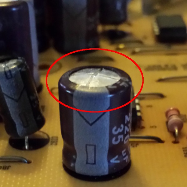
After confirming no grid shorts, open the electronics compartment. Critical warning: Capacitors may retain charge—always verify <1V with a multimeter before touching components. Look for these failure indicators:
– Bulging capacitors: Tops should be flat; domed or leaking electrolyte means immediate replacement
– Transformer damage: Discoloration, melted plastic, or burnt smell near the coil
– Circuit board scorching: Brown/black marks around high-voltage components
Failed capacitors cause 75% of non-zapping failures. They typically appear as small cylindrical components (0.47-1μF rating) near the transformer. If bulging or leaking, they’ve lost capacitance needed to build the lethal zap charge. The transformer (stepping 120V to 4,000V) often fails after rain exposure—check for cracked epoxy or charred windings. Replace any component showing physical damage; attempting repair risks fire.
Capacitor Testing Without Special Tools
While an ESR meter provides definitive testing, you can perform a basic check:
1. Discharge capacitors with 10kΩ resistor for 5 minutes
2. Set multimeter to capacitance mode
3. Measure value—should be within -10%/+20% of labeled rating (e.g., 0.47μF = 0.42-0.56μF)
4. If reading “OL” (open) or near zero, replace immediately
Never test capacitors while the unit is powered. If your multimeter lacks capacitance mode, replacement is safer than guessing—quality replacements cost under $5. Always match voltage ratings (use 4kV+ caps for Stinger models) and replace all capacitors in the voltage multiplier stack simultaneously.
Step 3: Verify Transformer and Voltage Multiplier Function
The transformer and diode-capacitor voltage multiplier (typically 3-4 stages) generate the killing voltage. Test transformer windings with your multimeter:
– Primary coil: Should read 3-5Ω resistance
– Secondary coil: Should read 1.5-3kΩ resistance
No resistance reading indicates an open winding requiring replacement. For the voltage multiplier, check each diode (usually 1N4007 types) in the ladder circuit. Set multimeter to diode mode—forward bias should show 0.5-0.7V drop; reverse bias should read “OL.” Replace any diode showing zero or infinite resistance in both directions. Critical note: Test diodes out of circuit for accuracy, as parallel paths can give false readings. If multiple diodes fail, inspect for moisture damage to the circuit board.
Why Transformer Failures Occur
Stinger transformers fail primarily due to two preventable causes:
1. Moisture ingress: Operating in rain or high humidity without GFCI protection causes internal arcing
2. Grid shorts: Insect debris creating sustained arcs overheats windings
Check for white crystalline deposits on windings—this indicates electrolytic corrosion from humidity. If the transformer smells burnt or shows melted tar, replacement is mandatory. When installing a new unit, ensure it’s rated for outdoor use (IPX4+ rating) and always plug into a GFCI outlet. Transformers cost $15-25—worth replacing if other components are intact.
Step 4: Test High-Voltage Output Safely
Only attempt this if comfortable with high-voltage work. With safety goggles on, use a non-contact voltage tester near the grid wires (never direct contact). A working zapper will trigger the tester from 1-2 inches away. For precise measurement:
1. Power on unit in dark area
2. Use high-voltage probe (1000:1 ratio) with multimeter
3. Measure between grid wires—should read 3,000-4,500V AC
Zero voltage? The issue is upstream in capacitors or transformer. Intermittent reading? Check for loose connections in the multiplier stack. Full voltage but no zap? Confirm grid spacing is exact—0.01″ misalignment prevents arcing. If readings are inconsistent, inspect solder joints on high-voltage components; thermal cycling often cracks them.
The Paper Ignition Test (Last Resort)
If other tests are inconclusive, perform this controlled verification:
1. Cut 1″x3″ strip of tissue paper
2. Hold with insulated pliers ¾” from grid
3. Power on unit—paper should ignite within 5 seconds
No ignition? Voltage is too low (<2,500V) due to capacitor or diode failure. Immediate ignition? Grid spacing is too wide—adjust to exact 0.25″. Warning: Never use fingers or conductive materials. This test confirms operational voltage but carries arc-flash risk—only attempt as final verification.
When to Replace Your Stinger Bug Zapper Instead of Repairing
Replace the unit immediately if you find:
– Cracked transformer casing
– Severe carbon tracking on circuit board
– Multiple failed capacitors in humid climates
– Any signs of internal fire damage
For newer models (under 2 years), repairs often cost 60% of replacement value. Prioritize safety over savings—faulty zappers cause 200+ electrical fires annually. If your stinger bug zapper light not working issue persists after capacitor and grid fixes, the control board likely has hidden damage. Modern units with microcontrollers (post-2015) rarely justify repair costs. A new Stinger unit ($35-60) includes updated safety features like automatic thermal cutoffs that prevent capacitor explosions.
Prevent Future Failures With Proactive Maintenance
Extend your zapper’s life with these weekly habits:
– Clean grids after heavy bug nights using soft brush and alcohol
– Store indoors during rain—even “weatherproof” units fail in sustained moisture
– Check grid spacing monthly with feeler gauges (0.25″ standard)
– Replace UV bulbs annually—degraded output reduces insect attraction by 40%
Always plug into GFCI outlets outdoors, and never operate within 5 feet of combustibles. During off-seasons, store disassembled in a dry container with silica gel. These steps prevent 90% of non-zapping failures by eliminating moisture ingress and debris buildup—the root causes behind the stinger bug zapper light not working confusion.
Restore your patio peace tonight by fixing that silent zapper. Start with grid cleaning and capacitor checks—you’ll resolve most non-zapping issues in under 20 minutes. Remember: when the UV light works but the zap fails, the high-voltage circuit holds the answer. Implement these targeted fixes, and you’ll reclaim bug-free evenings without replacing a single component. For persistent issues, consult the manufacturer’s warranty—many Stinger models include 2-year coverage against electrical failures.