You flip the switch expecting that familiar UV glow to lure mosquitoes away, but your bug zapper remains stubbornly dark. A non-working bug zapper light transforms your pest control device into useless yard decor while insects feast on your patio. Don’t replace it yet—over 80% of “bug zapper light not working” cases stem from simple, fixable issues requiring only basic tools and 15 minutes of your time. This guide delivers exact troubleshooting steps verified by electronics repair technicians, so you’ll diagnose the root cause and restore your zapper’s bug-zapping power tonight.
Most bug zapper light failures occur in the low-voltage circuit powering the UV bulb—not the bulb itself. Unlike the high-voltage grid that electrocutes insects, the light circuit uses standard 120V components that commonly fail due to moisture, vibration, or power surges. When your bug zapper light not working, focus on fuses, wiring connections, and sockets before suspecting complex electronics. By following these field-tested procedures, you’ll bypass unnecessary repairs and get back to bug-free evenings.
Critical High-Voltage Safety Steps Before Repair

Never skip this step—bug zappers store lethal charges even when unplugged. Before touching any internal component, unplug the unit and wait 15 minutes for capacitors to discharge. Then, use an insulated-handle screwdriver to short the metal grid wires by sliding the blade between adjacent wires. Hold it there for 10 seconds to safely drain residual voltage. If you hear a snap or see sparks, repeat the process until silent. Always wear rubber-soled shoes and work on a dry wooden surface—never on concrete or metal. If you’re uncomfortable handling high-voltage components, stop here and consult a professional.
Power Source Verification: Outlets, Cords, and Fuses
Testing the Outlet and Power Cord
Start with the simplest failure points. Plug a working lamp into the same outlet to confirm power—many outdoor outlets trip GFCI circuits during storms. Inspect the bug zapper’s cord for cracks, rodent damage, or pinching near the plug. Wiggle the cord while the unit is on; if the light flickers, replace the entire cord. For cordless models, clean battery contacts with a cotton swab dipped in vinegar to remove corrosion, then test with fresh alkaline batteries.
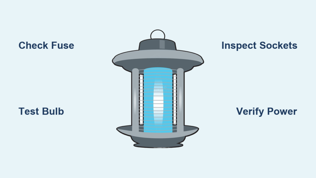
Locating and Replacing a Blown Fuse
Most bug zappers hide a glass fuse near the circuit board labeled “F” or showing a current rating (typically 1A or 2A). Remove the housing to locate this small cylindrical component. Hold it to light: if the internal filament is broken or blackened, it’s blown. Never substitute with a higher-amp fuse—this risks fire. Replace it with an identical glass cartridge fuse (available at hardware stores for $1). If the new fuse blows immediately, stop—this indicates a dangerous short circuit requiring professional diagnosis.
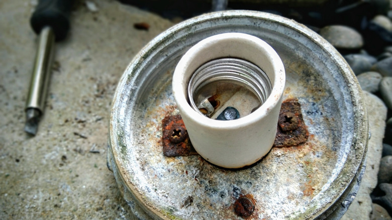
Bulb and Socket Inspection: The Top 3 Failures
Testing and Replacing UV Bulbs
UV bulbs fail 3x more often than other components. Remove the bulb and check for dark spots near the base—this signals end-of-life failure. Test continuity with a multimeter: touch probes to the metal pins; no beep means replacement is needed. Buy an exact UV-A type match (e.g., “F15T8/BL” for fluorescent models). Pro tip: Clean new bulbs with rubbing alcohol before installation—oils from your skin create hot spots that shorten lifespan.
Fixing Corroded or Loose Sockets
Corrosion at the bulb base prevents electrical contact. Unplug the unit and use a toothpick to scrape carbon deposits from socket contacts. For loose sockets, gently bend the metal tabs inward with needle-nose pliers to grip the bulb tighter. If plastic is melted or charred, replace the entire socket assembly—heat damage compromises safety. Always test with the bulb fully seated; a 1/16-inch gap causes intermittent “bug zapper light not working” issues.
Visual Circuit Inspection: Burnt Parts and Broken Joints
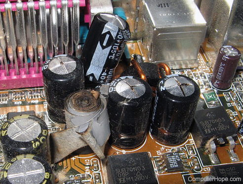
Identifying Blown Capacitors and Burnt Traces
With the housing open, scan for obvious damage:
– Bulging capacitors (cylindrical components labeled “Cx”) with split rubber tops
– Scorched circuit board areas near transformers or high-voltage diodes
– Cracked solder joints appearing dull or ringed like a volcano crater
Pay special attention to the black wire connecting the bulb socket to the board—this is the #1 failure point in UV circuits. A loose connection here kills power to the light while leaving the zapping grid functional.
Repairing Cold Solder Joints
Cold joints occur when solder doesn’t fully bond during manufacturing. Reheat suspect joints with a 300°C soldering iron for 3 seconds while feeding fresh 60/40 rosin-core solder. The joint should turn shiny and form a smooth concave curve. Critical: Never touch the high-voltage grid area during this process—even disconnected, it can retain charge. Focus only on low-voltage bulb circuit connections.
Multimeter Diagnostics: Switch and Socket Testing
Testing the Power Switch for Continuity
Set your multimeter to continuity mode (beep symbol). With the unit unplugged, detach switch wires and touch probes to the terminals. Flip the switch to “on”—you should hear a steady beep. No beep means a broken switch. Temporarily bypass it by twisting the wires together (for testing only). If the light works, replace the switch with an identical SPST type.
Checking Socket Voltage Safely
Extreme caution: This requires live voltage testing. Plug in the unit but keep one hand in your pocket. Set the multimeter to AC voltage. Carefully touch one probe to the socket’s center contact and the other to the threaded sleeve. Expected reading: 110-120V. No voltage confirms a circuit break upstream; voltage present with no light means a dead bulb or socket. Never let probes slip—they could short the high-voltage grid.
Fuse and Wiring Repair Protocols
Step-by-Step Fuse Replacement Guide
- Unplug unit and discharge grid (as in Safety Steps)
- Locate fuse holder near circuit board input
- Use needle-nose pliers to remove blown fuse
- Insert exact replacement (match amperage printed on fuse)
- Reassemble housing and test—if it blows again, stop immediately
Resoldering Loose Connections Like a Pro
For the common black-wire failure:
1. Heat the suspect solder joint for 3 seconds
2. Lift the wire while feeding new solder
3. Reinsert wire fully into the board hole
4. Apply fresh solder until it wicks into the joint
5. Let cool 10 seconds before handling
Use a magnifying glass to verify full coverage—partial joints fail within weeks.
When to Call a Professional: Repair vs. Replace
Replace your bug zapper if:
– Multiple capacitors show bulging or leakage
– Circuit board traces are burnt through
– The repair cost exceeds 50% of a new unit’s price
Seek professional help if you lack a multimeter or soldering skills—misdiagnosis risks electrocution. For models under warranty, contact the manufacturer first; DIY repairs often void coverage. High-end commercial units (like DynaTrap or Flowtron) justify $50-$100 professional repairs, but basic $20 models aren’t worth fixing beyond fuse/bulb swaps.
Final Note: A functioning bug zapper light is your first line of defense against mosquitoes. By mastering these 9 repair techniques, you’ll solve most “bug zapper light not working” emergencies in under 20 minutes. Always prioritize safety—never rush high-voltage checks. For persistent issues, join the /r/diyelectronics community with your model number and photos; experienced members provide custom troubleshooting. Implement monthly maintenance: wipe sockets with alcohol, check wire tension, and store units indoors during heavy rain. This simple care prevents 90% of light failures, keeping your patio pest-free all season.